

FAQs : Frequently asked questions on the topic of temperature measurement and the answers
What is a type K thermocouple? What is a bolometer used for? What do response times depend on? We answer the most frequently asked questions on the topic of temperature measurement in this section.
Require assistance with something specific? Call our central service number or the contact partner for your industry.

A thermocouple is a temperature sensor that generates a thermoelectric voltage depending on the temperature to be measured. The thermoelectric effect, otherwise known as the Seebeck effect, generates a signal.
In order to use the Seebeck effect, different metals first need to be in contact with each other. The corresponding combination for standard industrial applications is standardized in DIN EN 60584-1. Thermocouples may consist of metal and alloys, including nickel/nickel chromium (type K), iron/copper nickel (type J) or noble metals such as platinum / platinum with 13% rhodium (type R), each of which are individually connected to each other at the measuring tip, the hot junction, to form a closed circuit.
Our thermocouples are characterized by a uniquely strong signal, while noble metal thermocouples are significantly more accurate and temperature-resistant.
In order to ensure the thermocouple's measuring signal is correct, the temperature first needs to be determined as a reference junction at the transition between the thermocouple and the measuring device. All thermocouple measuring devices take this cold junction compensation (CJC) into account in the factory configuration.
A thermocouple relies on the Seebeck effect.
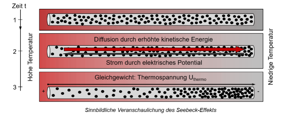
The freely moving electrons in a metallic conductor with a difference in temperature between the two ends are shifted from the hot end towards the cold end due to the excess energy. The resulting shift in charge leads to electrical potential between the two ends. This material-specific effect occurs in all metals and semiconductors.
To use the Seebeck effect, different metals need to be joined together. The junction between the two metals is brought to the measuring temperature with suitable thermal coupling. Due to the difference in temperature between the measurement point, namely the hot junction, and the connection to the measurement device, the cold junction, the charge shifts for both metals. The voltage build-up typically varies strongly due to the different thermoelectric properties of the metals. The difference in potential between the two thermoelectric materials can be measured as a thermoelectric voltage.
In order to standardize the thermoelectric voltage, the material pairings and the reference junction, i.e., the cold end where the signal is measured, are standardized at 0°C. Reference junctions are typically at ambient temperature for the majority of measuring devices used for industrial applications. As a result, the thermocouple produces less thermoelectric voltage than required to calculate the exact temperature according to the standard. To account for this, the measuring devices measure the terminal temperatures and computationally compensate for the missing thermoelectric voltage with 0°C in a process otherwise known as cold junction compensation (CJC).
Thermocouples are electrical contact thermometers that can, in principle, be used in all measuring systems for industrial and research-related purposes.
They are primarily used in applications involving high temperatures, strong vibrations or high oscillations, or where fast response times are required. Greater deviation is expected than with resistance thermometers, for example.
Thermocouples measure using points, making them ideal for sensitive temperature profile measurements.
Thermocouples can either be designed as immersion sensors or surface sensors, as direct or isolated sensors, or as hand-held measuring devices with two isolated test probes, for example. As a result, they are suitable for a wide range of applications in the following industries:
- Industrial furnace construction
- Plant/machine construction
- Automotive
- Chemicals
- Power plan engineering
- Glass
- Food
Thermoelectric voltage refers to the difference in electrical potential between the positive and negative conductor of a thermocouple, which builds up due to a difference in temperature between the measuring tip and the connecting contacts. The resulting voltage is generated by the thermoelectric effect, otherwise known as the Seebeck effect. The standard voltage tables for individual types of thermocouples are standardized in DIN EN 60584-1 with 0°C as the reference junction. If the reference junction is at another temperature, the missing or excess thermoelectric voltage needs to be arithmetically compensated for.
Generally speaking, a thermocouple can be laid with its base material from the measuring point to the control room. However, the sensor may not be flexible enough or simply too expensive, depending on the diameter, design and type of thermocouple. Just imagine the costs and amount of work required to lay a type R platinum thermocouple over 100 meters across the factory floor, or bending an 8.0mm thermocouple to follow the cable routing.
For this reason, thermocouple or compensation cables are used to bridge the distance between the measuring point or thermocouple and the measuring card. Beyond purely transmitting the signal, the cable is also required for signal generation to ensure the temperature difference between the cold end of the thermocouple and the intrinsic temperature of the measuring card can be compensated. The thermocouple and compensation cables therefore need to possess the same thermoelectric properties as the thermo material in the thermocouple.
While the thermocouple cable has the same thermo material as the inner conductor, only materials that possess identical thermoelectric properties as the thermo material are used for the compensation cable.
Using the same thermo material in the thermocouple cable improves the accuracy of the measuring chain.
That being said, the use of compensation cables remains justified due to their cheaper purchase price. For instance, noble metal thermocouples in particular only use compensation cables, as producing a thermocouple cable is simply not economical.
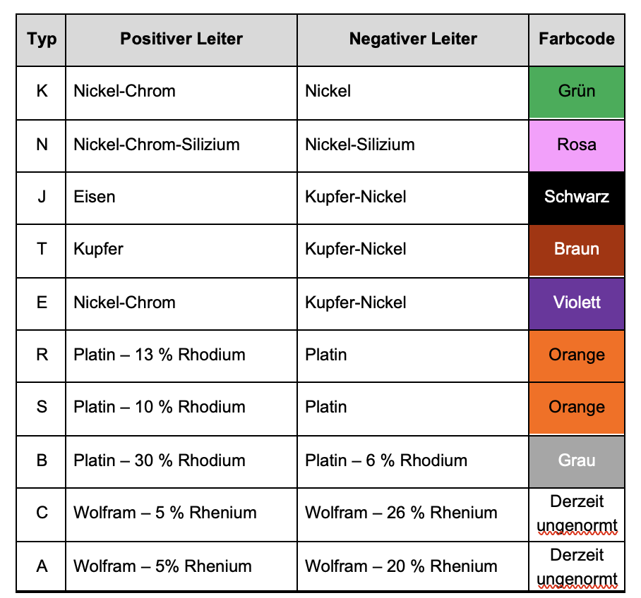
The color coding for thermocouple and compensation cables is standardized in DIN EN 60584-3.
Type K thermocouples are one of the 10 types of thermocouples standardized in DIN EN 60584-1. The type denotes the combination of materials used to produce the thermocouple. In a type K thermocouple, a nickel chromium alloy is used as the positive conductor and nickel as the negative conductor.
In Europe, this type is marked in green in accordance with DIN EN 60584-3. It is one of the most commonly used types for industrial applications.
The following types of thermocouples have been standardized:
Pt100/0 measuring resistors are electrical resistors routinely used as sensor elements in resistance thermometers for technical temperature measurement. This resistor is made of the purest platinum and reaches 100 Ohm at 0°C.
As the temperature rises, the intrinsic resistance of the Pt100 also increases, reaching 138.5 ohms at 100°C.
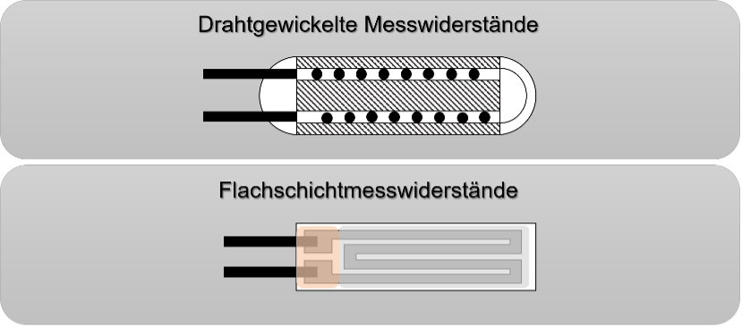
The Pt100/0 measuring resistor is available in two models as standard: as a wirewound resistor and a flat-film measuring resistor.
The wirewound resistor is wound around a ceramic or glass mandrel and protected from external influences by ceramic or glass housing.
A ceramic substrate is coated in platinum for the flat film measuring resistor. This platinum layer features meandering conductor paths and is sealed with ceramic or glass adhesive.
Both resistor types are equipped with pins.
A resistance thermometer is a type of electrical contact thermometer. It utilizes the dependence of the electrical resistance of metallic or semiconductor resistors on temperature.
The Pt100/0 resistance thermometer is the type most commonly used for industrial purposes, with basic resistance of 100 ohms at 0°C.
Pt1000, Pt500 or Ni100 measuring resistors and NTC or PTC measuring resistors are also used for industrial purposes.
When the temperature of the metals changes, so does their electrical resistance. The electrical resistance increases when the temperature increases and decreases when the metal cools down. The way in which electrical resistance changes depending on the temperature varies from material to material.
This effect is utilized in resistance thermometers. Certain requirements need to be met to achieve accurate measurements on this basis. To start off, a material with a known temperature behavior that can be calculated is required. Then the basic resistance of this metal needs to be precisely set at a defined temperature through calibration and adjustment. Finally, the temperature of metallic resistance must be very close to the true temperature of the medium to be measured.
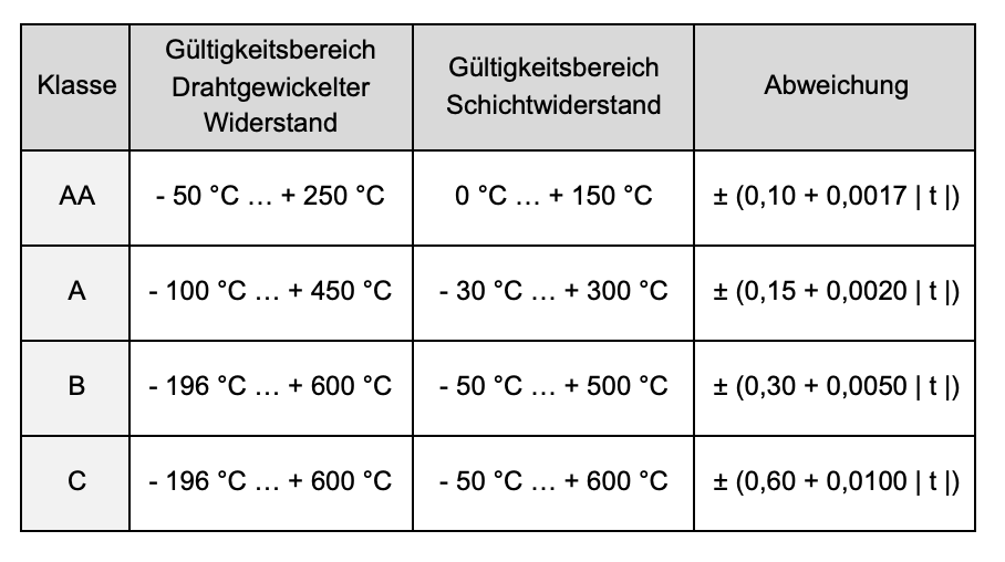
For Pt100/0 platinum measuring resistors, the first two requirements have been standardized in DIN EN 60751 and supported with a calculation function, temperature resistance tables and accuracy classes. The final thermal coupling requirements depend on a combination of the application situation and a fitting sensor design.
Depending on the manufacturing quality of the measuring resistors, resistance thermometers can be divided into different accuracy classes. According to the DIN EN 60751 standard, resistance thermometers have the following permissible deviations:
When the temperature of the metals changes, so does their electrical resistance. The electrical resistance increases when the temperature increases and decreases when the metal cools down. The way in which electrical resistance changes depending on the temperature varies from material to material.
This effect is utilized in resistance thermometers. Certain requirements need to be met to achieve accurate measurements on this basis. To start off, a material with a known temperature behavior that can be calculated is required. Then the basic resistance of this metal needs to be precisely set at a defined temperature through calibration and adjustment. Finally, the temperature of metallic resistance must be very close to the true temperature of the medium to be measured.
For Pt100/0 platinum measuring resistors, the first two requirements have been standardized in DIN EN 60751 and supported with a calculation function, temperature resistance tables and accuracy classes. The final thermal coupling requirements depend on a combination of the application situation and a fitting sensor design.
Depending on the manufacturing quality of the measuring resistors, resistance thermometers can be divided into different accuracy classes. According to the DIN EN 60751 standard, resistance thermometers have the following permissible deviations:
A traditional resistance thermometer consists of one or more measuring resistors, electrical conductors, a thermowell, insulation material and suitable connections.
In essence, resistance thermometers can be split into line sensors and measuring inserts. While measuring inserts are installed in fittings with a thermowell, connection socket and connection head and can be replaced at any time, line sensors consist of a flexible line and a sensor element.
Along with measuring resistance, the accuracy of the resistance thermometer is ultimately determined by the selected circuit type.
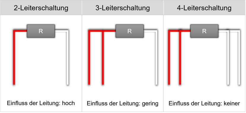
Two-wire circuits are the most cost-effective yet most inaccurate measuring method. The two connection pins on the measuring resistor are extended by one conductor and connected to the measuring device. This requires minimal material as the intrinsic resistances of the conductor are fully incorporated in the measurement signal. As a result, the conductors need to be as short as possible or have a large cross-section, or any errors need to be arithmetically compensated for.
The four-wire circuit requires the most materials and evaluation, yet yields the most accurate measurements. A smart combination of a constant current across the resistance provided by a red-white conductor pair and the measurement of the voltage drop across the measuring resistance by the second conductor pair ensures the intrinsic resistances of the conductors are fully compensated. The measurement signal is measured without any distortion.
The compromise between these two circuits is the three-wire circuit.
A bridge circuit such as the Wheatstone bridge, is used to compensate for the intrinsic resistances in a circuit. The challenge lies in the fact that the three conductors must be completely identical in terms of structure, material properties and external conditions to ensure measurements can be taken without any distortion. However, the differences arising from the actual design of the conductors and the actual operating conditions are significantly smaller than with the two-wire circuit.
Digital sensors are a combination of an analog sensor such as a resistance thermometer and a signal converter such as a measuring unit or a transducer. The transducer modulates the analog signal of the resistance thermometer into a discrete signal via a HART signal, for example. Digital displays in connection heads are also possible. Digital sensors require an external or an internal voltage source as well as a compatible communication interface.
NTC and PTC thermistors are sensors whose electrical resistance changes depending on the temperature. Two behaviors are possible in the process:
The resistance increases as the temperature increases. Conductivity is therefore best at lower temperatures. This behavior is exhibited by thermistors with a Positive Temperature Coefficient (PTC for short). Examples of PTC thermistors include metals such as the platinum in a Pt100/0.
NTC thermistors behave in exactly the opposite way. When the temperature increases, the resistance of the thermistors decreases – they exhibit a Negative Temperature Coefficient (NTC for short). As a result, conductivity is best at high temperatures. Examples of NTC thermistors include metal oxides/ceramics or semiconductors such as silicon.
In practical applications, both thermistor types can be used to measure temperatures. However, the partially strongly non-linear signal characteristics of NTC sensors must be taken into account.
The question of whether a sensor is active or passive depends on whether the sensor independently generates a signal and is therefore active, or a signal is generated using auxiliary energy, making the sensor passive.
Thermocouples are one example of active sensors as they generate thermoelectric voltage due to ambient conditions that can be displayed on a measuring device with a purely analog display.
Passive sensors traditionally include all resistance-based, capacitive or inductive sensors, and therefore also resistance thermometers. They require a measuring current that is fed via the measuring device. This auxiliary energy is then modulated due to environmental influences and can be evaluated as a signal. With passive sensors, self-heating needs to be taken into account as it can influence the measurement results. As a result, the measuring current for resistance thermometers is typically limited to ≤ 1 mA.
RÖSSEL-Messtechnik – your certified partner
As a leading manufacturer of temperature measuring technology for industrial and research purposes, we meet the strictest production standards. With internationally recognized approvals and calibrations, we offer quality you can rely on around the globe.